
ENGINEERING REPORT 2010
Adapted the January 2011 4150 Newsletter. By John Whitcomb
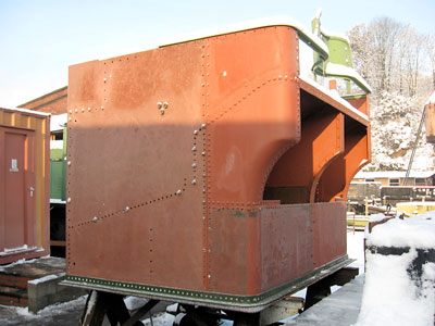 All of the steel sheets for the exterior of the bunker have now been delivered. The sheet which wraps around the base of the back of the bunker is some 10' long with two radiused corner sections, and the decision was taken to have it supplied in two sections, split vertically to the right of the centre line, with a small overlap which was then trimmed to provide an accurate fit. This ensured that the corners fitted tightly inside the angles which attach this sheet to the bunker base. The two sections were then accurately welded together by Bob Russell, and the end result can be seen here.
A great deal of drilling has been done on the bunker platework, as can also be seen in the photograph. Most of these are holes for half inch or three eighths inch rivets (one of these days we’ll need to work out exactly how many), but in the bunker base some much larger holes have been cut out by Terry Howes for the various water outlets and for the large rectangular-section balance pipes which carry water from the tanks to the bunker water space. At least the weight of this enormous sheet gets slightly less with every hole drilled!
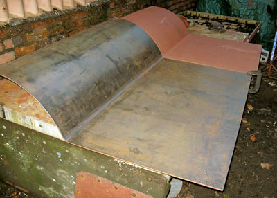
The three large baffle plates (two transverse and one longitudinal) which prevent water surge and support the centre of the coal plate, have had the necessary large holes cut in them for access into the inner depths of the bunker whenever the need arises. These are now in the container awaiting installation. The most recent sheet to arrive is the large (7 foot wide) sheet at the top of the rear of the bunker, which again has been made in two sections, for subsequent welding into one. Getting the profile of these correct is difficult to say the least, with opposing curves of different radiuses having to be rolled into the sheets. Our suppliers in Hartlebury have been very helpful in having them back twice for modification. Once these have been successfully test-fitted and drilled, we can move on to the remaining sheets to be replaced inside the bunker (much more straightforward!), namely a triangular-profile box section which fits over the sloping section of the loco main frames, and a 4ft by 7ft section of the coal plate, which we plan to weld into place as the final piece of the jigsaw, thereby giving good access to the inside of the bunker until the latest stage possible. The feasibility of this approach has been demonstrated recently at Bridgnorth by a similar procedure on the coal plate of the new tender tank for 2857, part of which was removed temporarily for access to platework beneath.
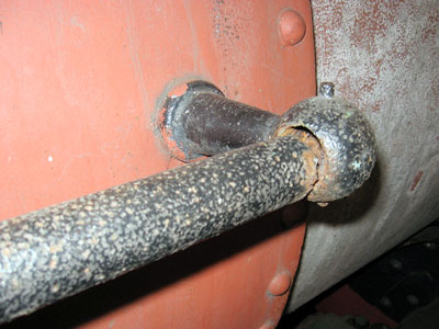
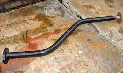 Paul Mason has made a superb job of fabricating the new steam heat pipework, involving a great deal of pipe bending and welding-on of new flanges. The copper pipe leading up to the steam heat control in the cab is the one remaining section of this pipework not yet completed, the 10ft length of pipe to form this having been delivered very recently. The rest of the steam heat pipework is all steel, as illustrated by Photo 3 which shows the length which leads up to the aforementioned copper pipe (the piece illustrated is the only section which is not yet in position on the loco – note that the top flange has been only temporarily tack-welded at this stage, to allow for final alignment with the copper pipe above it). Once again, we are grateful to ace welder Bob Russell for his finish-welding of the flanges to a very high standard.
 Attention then turned to the delivery pipes which carry water and steam at high pressure from the injectors forwards towards the clack valves which are mounted on either side of the safety valve, and whose role is
to admit the water/steam mix into the boiler. These are steel pipes of a non-standard size, and we were very fortunate that one of Alan Atkinson ’s neighbours, who had worked in tubes before retiring and had maintained his old contacts, was able to locate a couple of lengths which had been sitting for many years in a warehouse in Wolverhampton and were considered surplus to requirements. A chance conversation in Bridgnorth buffet about how we could get these to the SVR was luckily overheard by manageress Gloria, who mentioned that Doug who was also working there could probably collect them on the trailer of his 4x4, and so it transpired – 4x4 to Bridgnorth, train to Bewdley, and now sitting nicely in place on the loco. A very lucky chain of coincidences and thanks to all those involved! Being of high specification, these tubes have a very solid wall thickness of 5mm, and provided something of a challenge for Paul’s pipe-bending machinery, but the end result is excellent (including a 6” radius 90 degree bend where the pipe leaves the running plate and goes up through a 6 inch diameter vertical hole right through the middle of the tanks – not many people know that perhaps!). The flanges needed to attach these pipes to the injectors and to the copper pipes which run up through the tanks and round the boiler to the clack valves, have been laser-cut and arrived on site just before Christmas.
Attention then turned to the delivery pipes which carry water and steam at high pressure from the injectors forwards towards the clack valves which are mounted on either side of the safety valve, and whose role is
to admit the water/steam mix into the boiler. These are steel pipes of a non-standard size, and we were very fortunate that one of Alan Atkinson ’s neighbours, who had worked in tubes before retiring and had maintained his old contacts, was able to locate a couple of lengths which had been sitting for many years in a warehouse in Wolverhampton and were considered surplus to requirements. A chance conversation in Bridgnorth buffet about how we could get these to the SVR was luckily overheard by manageress Gloria, who mentioned that Doug who was also working there could probably collect them on the trailer of his 4x4, and so it transpired – 4x4 to Bridgnorth, train to Bewdley, and now sitting nicely in place on the loco. A very lucky chain of coincidences and thanks to all those involved! Being of high specification, these tubes have a very solid wall thickness of 5mm, and provided something of a challenge for Paul’s pipe-bending machinery, but the end result is excellent (including a 6” radius 90 degree bend where the pipe leaves the running plate and goes up through a 6 inch diameter vertical hole right through the middle of the tanks – not many people know that perhaps!). The flanges needed to attach these pipes to the injectors and to the copper pipes which run up through the tanks and round the boiler to the clack valves, have been laser-cut and arrived on site just before Christmas.
 We have recently had three more lots of pipe delivered, for new vacuum pipework and sand delivery pipes, and for handrails in the cab area and around the smokebox. The original vacuum pipe is in reasonable condition and there was much debate about whether or not it should be re-used. Re-using it, though, would always leave the possibility of undetected flakes of rust breaking off the inner surface of the pipe and lodging in the vacuum cylinder or brake valve – a situation which has caused problems at Bridgnorth on newly-restored locos in the past. Removal of the vacuum cylinder for remedial action is a major and very unwelcome task, to be avoided if at all possible. All-new pipework was therefore decided on as the safest option. There was no such deliberation though about the sand pipes, which had long since lost their straightness and circularity, and taken on a distinctly battered appearance. Nor about the handrails, which had rotted through completely in a number of places.
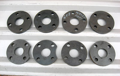
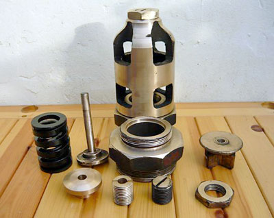 Gerald Peacock has been busy at home refurbishing the cylinder pressure relief valves. These can be considered as 'last resort' safety valves for the cylinders, in the event of undue pressure build-up, due, for example, to water being present and not being expelled as normal through the cylinder drain cocks. There are four valves in all, being located on both front and back cylinder covers. A number of parts were missing from these valves, but we now have a complete set of components thanks to the Erlestoke Manor Fund and Bridgnorth, with the exception of three spindles which Gerald is machining from 2" diameter stainless steel bar. The components that make up one complete valve are shown here.
Next in line are the cylinder drain cocks, six in all, for which we have rough castings requiring machining and assembly. Once again, the valve spindles will have to be machined from stainless steel bar, this time though from smaller diameter bar resulting in a lot less wastage of material. In both cases, we're grateful to Pete Simpson for donating the stainless steel. A new set of springs has been acquired recently, and the brass washers on which one end of the spring sits have been machined by Gerald from scrap boiler washout plugs which can't be re-used when the loco goes back into traffic - waste not, want not! The frames on which the drain cocks are mounted have already been overhauled and are in the container awaiting installation. Also in the cylinder area, Alan Atkinson has been tackling the cladding around the cylinder/valve chest castings, most of which has to be made from scratch, though the large sheets round the outside of the cylinders themselves were replaced some years ago and these can be re-used. Angle to provide strengthening round the vertical edges has been acquired and this will need some careful bending to achieve the required profile. The threads cut into the castings for the 1/2" bolts which secure the cladding have become worn over the years, to the extent that a number of the bolts now keep turning and fail to engage. Alan's solution to this problem is to use 'helicoils', an ingenious device whereby the hole is drilled out to a larger diameter, to receive a permanently fixed cylindrical insert, the inner face of which is threaded to accept a 1/2" bolt - very clever!
Dave Link's plans to tackle the crinolines which will form a framework for attaching the boiler and firebox cladding have been somewhat thwarted during the last twelve months by getting involved with other tasks like drilling and fitting the bunker sheets, and various welding and fabrication jobs, including the complicated section of running plate around the base of the steam pipes in conjunction with Terry Howes. Dave’s current task is fabricating the awkwardly shaped angles which secure the curved bunker sheet behind the top lamp bracket to the main coal plate. He's keen to get on with the crinolines though, and we'll have to ensure time is available for this job during 2011.
As regards cab fittings, Dave Insull, with welcome assistance from Ian Bromley at Bridgnorth, has virtually completed machining the complexities of the brake valve, and is well advanced in machining the blower valve, in both cases from castings acquired by the Fund some time ago. We were delighted when a Fund member responded to our appeal in the last newsletter for someone to sponsor the purchase of a new combining valve/jockey valve, one of the few cab fittings we didn’t possess, either in complete or raw casting form. It’s currently being machined, and should arrive during 2011 ready to fit straight onto the loco. Negotiations are under way to exchange some of our surplus Great Western spares for the remaining items we are still lacking, the most significant recently being the cast pedestal to which the water gauge assembly is attached, complete with its two test cocks. The major item not yet tackled in this area is the sight feed lubricator, on which we hope to make some progress during the coming year.
Purchases during the next twelve months will include a number of lengths of copper pipe in various sizes and gauges to replace those which were removed from the loco at Barry before it was purchased by the Fund. Specifically, these are (i) from the injector steam valves to the injectors (these are the vertical pipes which show up prominently on the footplate, and pass either side of the firehole door), (ii) from the base of the bunker water space to the water valves mounted under the cab floor, (iii) from the water valves to the injectors, and (iv) from the steel delivery pipes already described, up through the tanks and round the boiler to the clack valves. In all cases a pair of pipes is required, a consequence of steam locos having most things duplicated on both sides of the engine. The price of copper has risen to alarming levels, notwithstanding worldwide recession, so if any of you are able to buy some extra shares to help cover the cost, we’d be extremely grateful. Whilst our bank balance might look healthy, we’re very conscious of the need to conserve as much of it as possible for the boiler when the time comes.